Triple
Floppy Tape Controller
|
|
Back in the olden days ... when floppy tape drives were the rage ...
tapes were preformatted for customers one at a time. One PC was dedicated to
one tape drive formatting one tape.
|
 |
|
The design consists of three floppy controller chips each
with dedicated IRQ and DMA channels.
Three half-high floppy tape drives and a half-high
floppy drive fit nicely into the two
full-high bays provided by the [now vintage] PCs of the time.
I used P-CAD schematic capture and PCB layout software.
The wire-wrapped board was implemented from
a P-CAD schematic printout.
|
|
 |
|
By carefully documenting and incorporating the required changes found during the prototype stage
back into the schematic,
the first PCB run was perfect.
|
|
 |
|
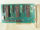
The picture at the left shows the top of a completed PCB.
Click on the picture for a larger view.
|
|
 |
|
The picture at the left is the top of a bare PCB
(What happens when you click on it?).
|
|
 |
|
The picture at the left shows the back of the completed PCB.
So the project's completed -- NOT! Now it's time for the firmware.
|
|
|
FIRMWARE
|
|
Three floppy tape drives were connected to the controller, each operating independently, one from the other.
MS/PC-DOS was not multi-tasking so a realtime preemptive multitasking kernel was used to implement
three independent floppy tape processes.
|
|
A character-based windowing application (using Borland C++ application framework)
was developed to control the tape formatting tasks.
|
|
COMMERCIAL: I was responsible for, and performed, all aspects of the project including
conception, hardware design (plus implementation and debugging),
schematic capture, PCB layout,
firmware design (plus implementation and debugging), and product testing.
And stuffing the PCB ... it goes without saying!
|
|
THANKS: Thanks to Larry Santellan for his P-CAD guidance.
There is no way the PCB would have been completed without his help and guidance.
"Thanks" doesn't quite say it.
|


